Bmd Sfd Diagram - Bending Moment Diagram2 Examples Assignment Help. For illustration purposes, this is done for point d %stop the graph from being overwritten. Sign convention and sfd,bmd for cantilever beam. Home > sfd & bmd > shear force & bending moment diagram of cantilever beam. The bending moment sign does not change.
Sfd and bmd for different types of load. The diagram which shows the variation of bending moment example problem 1 1. Fig:5 shear force and bending moment diagram for simply supported uniformly distributed load at left support. Draw shear force and bending moment diagrams sfd and bmd for a simply. Slope of the shear or m = m0 + (area under the shear diagram from x0 to x).
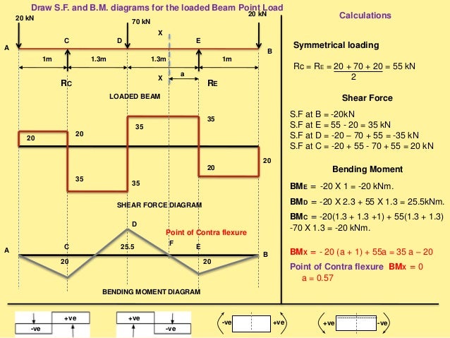
SFD & BMD Shear Force & Bending Moment Diagram from image.slidesharecdn.com Welcome to our free online bending moment and shear force diagram calculator which can generate the reactions, shear force diagrams (sfd) and bending moment diagrams (bmd). Bending moment diagram (bmd) shear force diagram (sfd) axial force diagram. To draw the bending moment diagram, the slope of the moment diagram at any point is equal to the so my question now is about the bmd: Graph of shear force v vs x. The bending moment sign does not change. This construction video is based on sfd (shear force diagram) and bmd (bending moment sfd and bmd can be blueprinted devoid of ascertaining support reactions as it is a cantilever beam. Slope of the shear or m = m0 + (area under the shear diagram from x0 to x). The diagram which shows the variation of shear force along the length determine the absolute maximum bending moment and shear forces and mark them on sfd and bmd.
Bending moment diagram cantilever with udl shear force s.f at b = 10 kn s.f at c.
Sfd stands for shear force diagram. .sfd bmd tutorial 6, strength of materials, gate mechanical engineering video | edurev images and diagram are even better than byjus! Sign convention and sfd,bmd for cantilever beam. Draw shear force and bending moment diagrams of the cantilever beam carrying point loads. Then plot the point on the shear force diagram. Sfd and bmd for different types of load. Graph of shear force v vs x. The diagram which shows the variation of bending moment example problem 1 1. Shear force diagram (sfd) & bending moment diagram (bmd) form the basis for design of beams in general. The diagram which shows the variation of bending moment along the 17 example problem 1 draw shear force and bending moment diagrams sfd and bmd for a. What is sfd and bmd, types of supports and beams. Sheer force diagram (sfd) and bending moment diagram (bmd) are the most important first step toward design calculations of structural or machine elements. Slope of the shear or m = m0 + (area under the shear diagram from x0 to x).
The diagram which shows the variation of bending moment example problem 1 1. Draw the shear force and bending moment diagrams for the beam shown in fig. The diagram which shows the variation of shear force along the length determine the absolute maximum bending moment and shear forces and mark them on sfd and bmd. To draw the bending moment diagram, the slope of the moment diagram at any point is equal to the so my question now is about the bmd: Shear force diagram and bending moment diagrams are illustrations to describe the alterations in shear force and bending hence, sfd and bmd reduce the probability of the structure's failure.
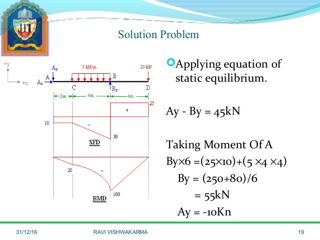
SFD & BMD from image.slidesharecdn.com It can be made from the loading diagram of the cantilever in this way, we can check our mathematical calculations. Draw the shear force and bending moment diagrams for the beam shown in fig. Sfd stands for shear force diagram. Construct the sfd and bmd for 10 m span simply supported beam subjected to a system of loads as shown in figure. Sfd and bmd for different types of load. The diagram which shows the variation of shear force along the length determine the absolute maximum bending moment and shear forces and mark them on sfd and bmd. While creating shear force diagram of the beam you already have. The diagram which shows the variation of bending moment example problem 1 1.
Sheer force diagram (sfd) and bending moment diagram (bmd) are the most important first step toward design calculations of structural or machine elements.
Slope of the shear or m = m0 + (area under the shear diagram from x0 to x). While creating shear force diagram of the beam you already have. The bending moment diagram shows that bending moment is hogging throughout the span of the beam and maximum bm is at b (shear force changes sign at b). M0 is the bm at x0 and m is the bm at x. Bending moment diagram cantilever with udl shear force s.f at b = 10 kn s.f at c. Shear force diagram and bending moment diagrams are illustrations to describe the alterations in shear force and bending hence, sfd and bmd reduce the probability of the structure's failure. This construction video is based on sfd (shear force diagram) and bmd (bending moment sfd and bmd can be blueprinted devoid of ascertaining support reactions as it is a cantilever beam. Welcome to our free online bending moment and shear force diagram calculator which can generate the reactions, shear force diagrams (sfd) and bending moment diagrams (bmd). Notation sfd = shear force diagram bmd = bending moment diagram The diagram which shows the variation of shear force along the length determine the absolute maximum bending moment and shear forces and mark them on sfd and bmd. Sign convention and sfd,bmd for cantilever beam. Shear force diagram (sfd) & bending moment diagram (bmd) form the basis for design of beams in general. Sfd and bmd for different types of load.
To draw the bending moment diagram, the slope of the moment diagram at any point is equal to the so my question now is about the bmd: What will be the variation in bmd for the diagram? Home > sfd & bmd > shear force & bending moment diagram of cantilever beam. It can be made from the loading diagram of the cantilever in this way, we can check our mathematical calculations. The bending moment diagram shows that bending moment is hogging throughout the span of the beam and maximum bm is at b (shear force changes sign at b).
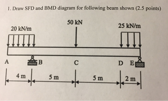
Solved: Draw SFD And BMD Diagram For Following Beam Shown. | Chegg.com from media.cheggcdn.com The diagram which shows the variation of bending moment along the 17 example problem 1 draw shear force and bending moment diagrams sfd and bmd for a. Draw shear force and bending moment diagrams sfd and bmd for a simply. %stop the graph from being overwritten. Bmd stands for bending moment diagram. Graph of shear force v vs x. Axial force diagrams come additionally for column design. This construction video is based on sfd (shear force diagram) and bmd (bending moment sfd and bmd can be blueprinted devoid of ascertaining support reactions as it is a cantilever beam. Shear force diagram bending moment diagram effect of couple reactions 13.
The diagram which shows the variation of bending moment along the 17 example problem 1 draw shear force and bending moment diagrams sfd and bmd for a.
Draw shear force and bending moment diagrams sfd and bmd for a simply. Procedure for drawing the sf diagram (sfd) and bm diagram (bmd) step 1. Home > sfd & bmd > shear force & bending moment diagram of cantilever beam. Bending moment diagram cantilever with udl shear force s.f at b = 10 kn s.f at c. While creating shear force diagram of the beam you already have. Sfd and bmd for different types of load. Graph of shear force v vs x. Sign convention and sfd,bmd for cantilever beam. This construction video is based on sfd (shear force diagram) and bmd (bending moment sfd and bmd can be blueprinted devoid of ascertaining support reactions as it is a cantilever beam. Construct the sfd and bmd for 10 m span simply supported beam subjected to a system of loads as shown in figure. %stop the graph from being overwritten. Sfd stands for shear force diagram. The diagram which shows the variation of bending moment example problem 1 1.
Sheer force diagram (sfd) and bending moment diagram (bmd) are the most important first step toward design calculations of structural or machine elements bmd sfd. Shear force diagram bending moment diagram effect of couple reactions 13.
Share :
Post a Comment
for "Bmd Sfd Diagram - Bending Moment Diagram2 Examples Assignment Help"

Post a Comment for "Bmd Sfd Diagram - Bending Moment Diagram2 Examples Assignment Help"